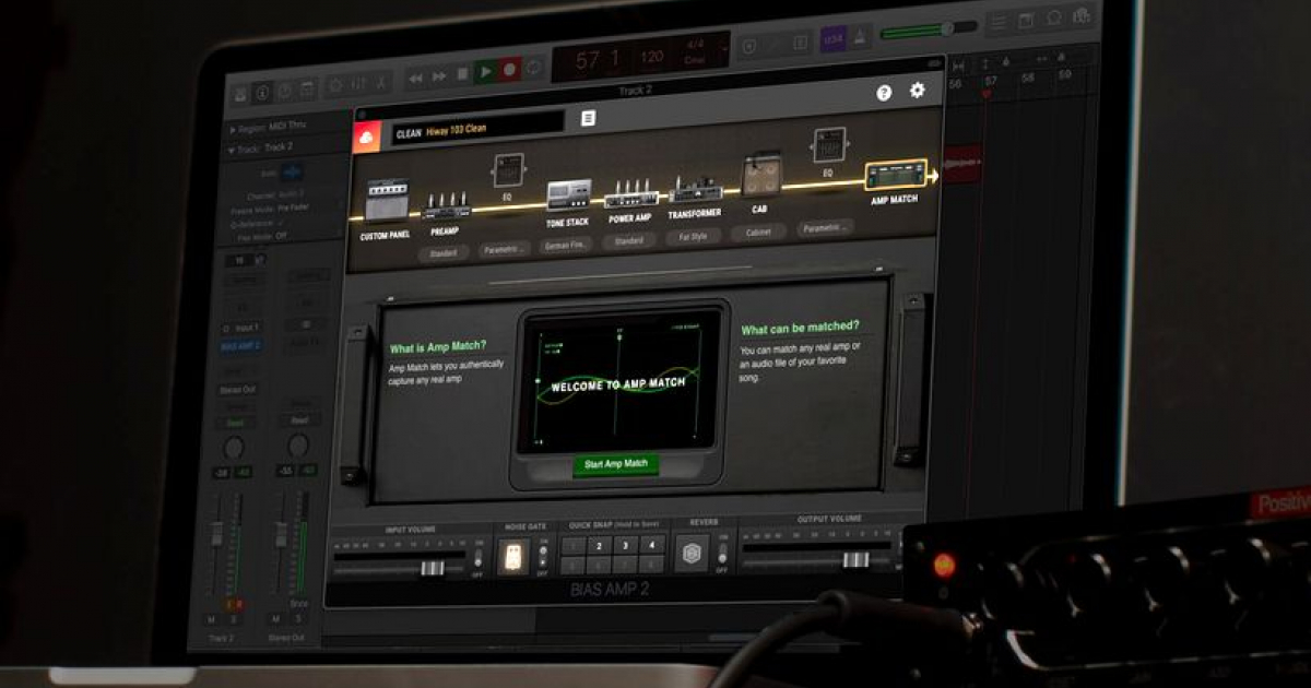


After the huge success of Amplitube 2, IK started releasing different high-end guitar and bass emulating software, including Amplitube Live 2, Amplitube Jimi Hendrix, Amplitube Metal, Ampeg SVX and Amplitube Fender. That was its kick off point of the company to the digital music world.
#Bias amp 2 stealth plug software#
3 years after that, because of fierce competition from companies such as Line6, Native Instruments and others, they released Amplitube 2, one of the most powerful and accurate amp modelling software packages at the time. With the release of Amplitube 1 in 2002, they started growing and expanding. In 1999 they released T-racks, which is an analog desktop mastering interface. In 1998 they released their first product, the Groove Maker, which was a loop-remixing package. Founded in Italy (Modena) in 1996 with goals to help musicians, producers and songwriters, IK Multimedia has been providing hardware and software for home and studio recording. Cut off the normal bias cable that links the two sockets (blue color), then solder the pro-bias output cable from the pro-bias module to the pin for the bias.Ik Multimedia is undeniably one of the leading companies of the 21st century for guitar and bass amplifier emulation, in the digital world. The easiest way is to use the right side socket. Lastly, connect the pro-bias output on one of the headphone socket in the front panel. The board underside should look like this:
#Bias amp 2 stealth plug install#
Then install the pro bias on the ground hole using a metal spacer. And solder an output cable for the pro bias (~ 30cm). First, solder the AC input cable for the pro-bias module. The next path is to install the module in position. Then, solder connecting cable on the AC input hole (~4cm). To ensure good contact on the ground hole, lay some solder around the ground hole. Make sure that those holes intersect the paths for the AC and the ground, as appropriate. The next step is to drill two holes on the amplifier PCB: Ground will be connected with a metal spacer, which will also serve as mounting points for the pro bias module. To simplify the process, only the AC input will be connected with a cable. Ground can be obtained from the black cable or one of the ground path from the PCB. On the SRM-1/Mk2 amplifier, AC input can be obtained from one of the yellow cables which is a cable from the transformer output.

Make sure that the spacer is installed tight! Then install metal spacer on the hole, as illustrated: I’m using a cable pad to make a circular trace on the ground hole, as illustrated below: Red lines are connecting lines below the breadboard, blue lines are legs of each components.įor the ground hole, make a 3mm hole on the breadboard. Solder the components on the breadboard, according to the layout. Heat level on each resistor is minimalized so that the voltage going through each resistor is not more than 350V.ĭ1, D2: 1N4007 (or other diodes with ratings above 800V)īreadboard: Independent pad holes, 5mm distance between holes Arc happens when a high voltage path lies too close to ground, enabling an electrical discharge from the high voltage path to ground. The layout above has been designed to minimalize arc and heat on the resistors. Please click on the image to see a larger size.


 0 kommentar(er)
